Beranda » Multi-color LED Driver Schematic

Multi-color LED Driver Schematic

Multi-color LED Driver Schematic

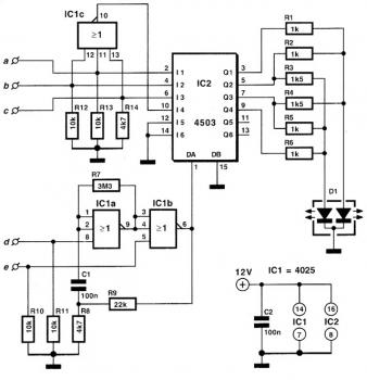
Have you ever wondered how many various colours can illuminate a LED? One, two or possibly three? Making this simple circuit, you will discover it a lot more. The important component in this design is a dual LED. One such accessory includes two inside the 'slices' of different diode LED, that each and every of them produces a different color (commonly green and red). For the drive needs three pins, a common cathode and two separate roots. In this way every single of the two integrated diodes can light up as independent of one another. You'll find only two colors that may create this dual LED.


Setting appropriate percentage of the currents flowing via two separate channels of the POY is, we have other from pure green and red, orange (IR = 21G) and yellow (IG = 2IR). In this circuit, the anodes of the double LED driven by the outputs a six-point buffer tri-state technology CMOS. As opposed to most integrated family of CMOS 4000, the 4503 applied here, can supply many different loads on high currents of the order of 10 mA. The stream that goes towards the two diodes is limited by the resistors R1 to R6 whose specific values are those that attain the distinct colors and changing brightness them. The circuit was originally created to display three various situations, each expressed their the presence of logical '1 'in one of the inputs a, b, c. The entries are able to activate only one of every single time, and if none of them had been excited, a NAND gate (IC1c) ensured that the LED 'to create fourth color. In the improved version we present these days, the circuit has added another level oscillator (IC 1 a and IC1b), which produces about two pulses per second. The pulses are introduced in the entrance activation OA (pin 1) of 4503, resulting in colorful flashes. The oscillator is controlled by the of logical statements applied to the inputs 'd' and 'e'. If both are simultaneously logical '1 ', then each the oscillator and also the buffers of 4503 stay inoperative. If e = 1 and d = 1, then all buffers are driven in a state of high resistance plus the circuit absorbs the least feasible electric current (standby). The power supply circuit was initially set at 12 Volt, but all of the components that are able to work equally properly with any voltage in between 5 Volt and 16 Volt.
Labels

AC ADJUSTMENT Advisories Air Conditioner AKARI AKIRA kadang tidak bisa start alarm Apps ARTIKEL atx audio Audio Power Amp Bagian Horisontal BASIC battery charger Bedah Electronic BELTRON ( Belajar Electronica ) BIKIN FOLDER WARNA WARNI biquad BUKA MENU SERVICE TV butuh bantuan nih....... cable checker cara membuka ic mpeg CARA MENGATASI VCD SAMSUNG STANBY CATATAN KECIL ceiling fan control motor 1 fase control motor 3 fase CRT CRT-YOKE-SOKET CRYSTAL CUSTOMER-SERVICE DATA-DATA Default Setting Eprom TV Defleksi DIGITEC-POLYTRON Disassembly Guides DivX DO IT YOUR SELF DVD DVD MATSUNICHI DVD LG model HT762TZ home theater stanby +tidak keluar gambar DVD samsung p-181 standby EEPROM electronic components Elektronic ESR-meter Evaporator FBT FBT-HIGH VOLTAGE Flashfiles Flyback flyback transformer fm Freezer freon fun circuits Gadget gambar cacat pada dvd DAT Gas beracun GEJALA KERUSAKAN GENERATOR gsm software high voltage HORISONTAL hp tx1000 Iklan Gratis INFO Info produk Info Technology Info. Info.Technology Instrument intercom Internet inverter irda jangan buang mpeg rusak jumper ic mpeg vcd yang hilang gambar Keluargaku Kerusakan vertikal tv sharp wonder Knight KOMPONEN kompresor KONKA KULKAS Kursus 60 detik Laptop LCD LCD Repair LDP LED and Light LG hilang gambar Log LUCKY-GOLDSTAR m1-da MEMBUKA TV CHINA YANG TERKUNCI mempercepat open close menambah USB pada MPEG dvd mengatasi dvd yang sering no disc mengganti ic sunplus karena gambar hilang MENU SERVICE CODE Mesin cuci MIKROKONTROL misc Modifikasi monitor monitor CHINA monitor GTC monitor LG Monitor Repair-ASIATECH Monitor Repair-GTC Monitor Repair-Hp Monitor Repair-LG Motor 3 fase Motor spin Motor Washing MP3/MP4/MP5 NO DISC notebook optical mouse Original oscillator PANASONIC Pc utilities pengalaman pribadi PERSAMAAN FLYBACK Pesanan skema PHILIPS pic microchip PIC16F pin tabung crt plasma tv POLYTRON Pompa air Power Inverter power supply POWER-SUPLY PROBLEM NO DISC DAN PROBLEM OPEN CLOSE PADA VCD AUTECH projector PROTEK psu Radio rangkaian control motor RASTER-BLANK Refrigerant Relay MK2P remote controlled repair Repair Guides REPAIR-TIPS ROM SAMSUNG SANYO SCHEMA Schematics servic TV JVC Service Antena Parabola Digital Service Centre Service Listrik Jogja Service Listrik Sleman service menu Service mesin cuci jogja Service mesin cuci Sleman SERVICE MODE Service Mode TV Service pompa air Jogja Service Sound Sistem Mobil Service Televisi Service VCD / DVD ServiceTV Servis Servis Mode servis mode tv cina SHARP SHARP chassis DUNTKE134WE Show Case Skema TV Software SONY sony tidak bisa start lagi SOUND (SUARA) Sparepart spdif sunplus flash programmer SV 220 TCL Technology Teknik Teknisi telephone terkadang bisa tapi 10 detik +/- mati Timer Spin Timer Washing. TIP DAN TRIK Tip's Tips tips and tricks Tips-Trik Tips. Tools TOSHIBA toslink touch switch Transistor transmitter triac Troubleshooting TUNER-VIF tv TV akari TV CHINA TV CINA TV GOLDSTAR TV JVC TV KONKA TV LG TV LG HORIZONTAL SELALU RUSAK TV PANASONIC TV PHILIPS TV POLYTRON Tv Repair-AIWA Tv Repair-AKARI Tv Repair-AKIRA Tv Repair-DETRON Tv Repair-LG/GOLDSTAR Tv Repair-PANASONIC Tv Repair-POLYTRON Tv REPAIR-SAMSUNG Tv Repair-SANYO Tv Repair-SHARP Tv Repair-SONY Tv Repair-TOSHIBA Tv Repair-TV CHINA TV SAMSUNG TV SANKEN TV SANYO TV SHARP tv sony TV TCL TV TOSHIBA universal remote kontrol VERTIKAL vga video VIDEO-CHROMA Warnings Water Heater WD 40 wlan antenna Zic
Diberdayakan oleh Blogger.